The following is a short summary of my efforts related to using a microcontroller for controlling some of my leg muscles.
Motivation
I find the idea of compensating for physical inability by attaching computers to the human body quite fascinating. In this post we are continuing this journey by trying to activate the muscle activation logic by use of a microcontroller.
What I Currently Use
The current version of the Active Muscle Stimulator is somewhat compact, and the logic is implemented into a Raspberry Pi Zero WH with a 1 GHz processor. Interestingly, it will not be long before I can celebrate having run 250 km supported by an Active Muscle Stimulator (at the time of writing, the status was 215.4 km).
A quick summary of the existing solution goes as follows: It is initially programmed via a small Bluetooth controller. It is located in a running waist pack, with a wire going to each leg for triggering my tibialis anterior muscles. It has an EMS module, which generates the electric impulse for the electrodes, but the electrode wires are passing relays controlled by the computer. The computer can sense movement, and an advanced algorithm is responsible for understanding the movement data and turning on and off the relays are the right time during the movement. It has to be right, or I would probably fall.
Can We Do Better?
When taking a look at the device, I often consider how it might be smarter if it we could transition into something with a lower power consumption, possibly comprising of several devices what are connected wirelessly.
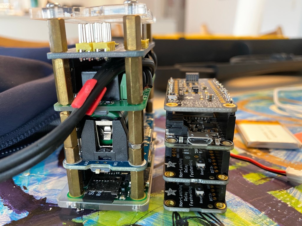
I think a multi-node implementation with wireless communication between the nodes might be the long term goal. But as a first step, my plan would be to transition the existing solution to a microcontroller platform. For this purpose I have been investing various controller boards, and I eventually came across Adafruit Huzzah32, a so-called Feather Board based on the ESP32 processor. This board does not come with an IMU (Inertial Measurement Unit), so I would have to extend it with so-called FeatherWing boards for adding IMU as well as relay functionality. With its dual core 240 MHz processor, its computational power might be comparable to the Raspberry Pi when we disregard the OS overhead.
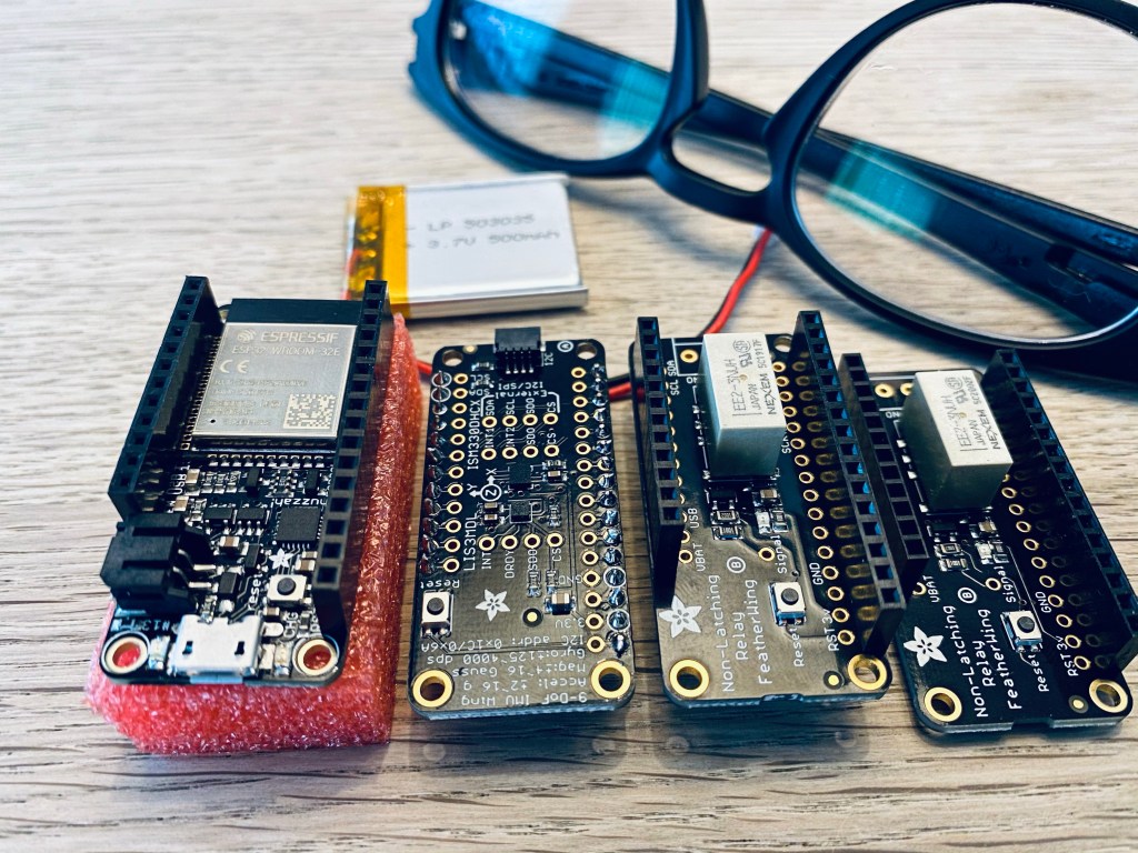
After having completed the initial header soldered, these boards are now stackable, and we can now start looking at how to program a Microcontroller for the purpose of controlling leg muscles.
Pre-Development Investigations
Before we can start the development of Active Muscle Stimulator software on this hardware, we need to do a few things. The plan would be something like figuring out the following:
- Development Environment
- Controlling Relays
- Using the IMU
- Using a Bluetooth Controller
1. Development Environment
I found that this board could can run under at least two different platforms: Arduino and ESP-IDF.
When trying the Arduino platform for this hardware, the amount of flash storage required for an empty application already seemed quite unreasonable. So even though it would be possible to run existing Arduino libraries with little to no custom coding, this is not the most flexible solution.
I instead tried out the ESP-IDF platform (Espressif IoT Development Framework). It is based on FreeRTOS with a large set of configurations for tweaking and turning on and off various features. In many ways, it is similar to compiling a Linux kernel with menuconfig and all that jazz. Being in complete control of the underlying system is very useful. For instance, I immediately tried changing the internal clock to 500 ticks per second instead of the default 100 ticks per second, and it worked smoothly.
During this investigation I have gotten to love running PlatformIO system running under Visual Studio Code, and luckily it also supports ESP-IDF. Unfortunately, I would need additional hardware for attaching a debugger to the microcontroller, so for now I will rely on the software being without bugs – or at least with the possibility of reading the relevant error information via the serial log messages.
2. Controlling Relays
It was super easy to add a few wires to the relay boards and instructing the controller to turn on and off the relays. We will try to settle with one relay per channel, probably by using a small resistor to short circuit the electrode connectors when they are not active. It has to be safe touching the electrodes when the device is idle.
3. Using the IMU
Since this is the third IMU I have worked with, it turned out to be surprisingly easy to hook it up. I found a standard C driver from IT (the chip manufacturer) and added it to the project with no code changes. But I added a few additional methods to be called when reading the IMU data. Basically, the entire configuration is happening via the driver, and the high performance reads are happening via a slightly optimized implementation.
The data being communicated from the IMU is being transmitted as 6 16 bit integers (three accelerations and three rotations). In order to get the best result, the ranges for these values must be configured as to avoid overflow (like when a microphone distorts when peaking).
In addition, the IMU has high pass and low pass filters. We probably would like to enable these, so that minor changes in the mounting angel of the device only results in limted output value changes.
It is possible to add wires to pins for enabling SPI with interrupts for faster communication between the IMU and the microcontroller. However, in order to keep this as simple as possible, I decided to use the I2C interface, which works without the need for additional wires and pin configurations. I could take a look as SPI some other time.
It seems apparent how much smaller the resource consumption is when communicating with external hardware in a microcontroller, where we don’t have to transition between user space and kernel space all the time. Such process isolation does not exist in microcontrollers, and thus the microcontroller CPU consumption for I2C communication seems quite limited.
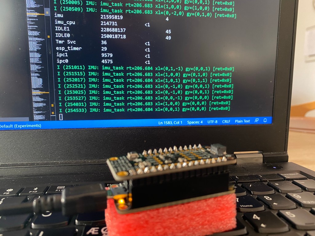
I haven’t used the FreeRTOS processor runtime statistics feature before, so I have little knowledge of its precision. If we assume that our task was waking up 208 times a second, it might be that the underlying timer only supports measurement of CPU usage in units of 1/2500 sec. When activating the IMU task 208 times a second, this corresponds to being active within 208 out of the 2500, resulting in an estimated CPU usage of 8%. If this is the case, there is probably a configuration option of the platform, which enables better tracking accuracy. I will need to investigate this further at some point.
4. Using a Bluetooth Controller
Before starting on this project at I had absolutely no knowledge on the internals of Bluetooth, but quite a lot of knowledge would be required before I would be able to attach a game controller to the microcontroller.
For now, I will summarize the efforts as follows. It looks like the Huzzah32 controller does Bluetooth nicely. I managed to adjust one of the code examples and pair my Bluetooth Controller with the microcontroller. It even remembers the pairing (by storing some data on the flash, I assume).
Since all the components seems to be working nicely, it is now time for adding some smart mathematics. More on this on the next posting.
